We’ve got a tag for that
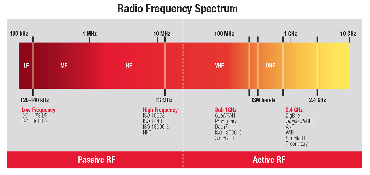
RFID tags come in all different sizes, shapes, and materials. They vary in capabilities based on the frequency.

Tagging services and solutions
- Site surveys
- Set-up
- Installation
- Configuration
- Implementation
- Management
- Support
Types
- UHF
- HF
- LF
- Glass
- Plastic
- Rubber
- Metal
- TPE & More
Request a FREE assessment of your business.
Passive tags are comprised of three elements: an integrated circuit or chip, an antenna, and a substrate.
The Chip
The RFID chip stores data and perform specific tasks. Depending on its design, the chip may be read-only (RO), write-once, read-many (WORM), or read-write (RW). Typically, RFID chips carry 96 bits of memory but can range from 2-1000 bits.
The Antenna
Attached to the chip is the second component, the antenna, whose purpose is to absorb radio-frequency (RF) waves from the reader’s signal and to send and receive data. Passive RFID tag performance is strongly dependent on the antenna’s size: the larger the antenna, the more energy it can collect and then send back out. Larger antennas, therefore, have higher read ranges (although not as high as those of active tags).
Antenna shape is also important to the performance of the tag. Low- and high-frequency (LF and HF, respectively) antennas are usually coils because these frequencies are predominantly magnetic in nature. Ultrahigh-frequency (UHF) antennas, on the other hand, look similar to old-fashioned TV antennas (“rabbit ears”) because ultrahigh frequencies are solely electric in nature.
The Substrate
The third component of a passive RFID tag is called a substrate, which is commonly a Mylar or plastic film. Both the antenna and the chip are attached to the substrate, which may be thought of as the “glue” that holds all of the tag’s pieces together.
In contrast to active RFID tags, passive tags are usually smaller and less expensive.
Like passive RFID tags, active tags have both a microchip and an antenna. The chips, however, are usually larger in size and have greater capabilities than the RFID chips in passive tags.
Active tags diversely have two additional components that differentiate them from passive tags: an onboard power supply and onboard electronics.
The Onboard Power Supply
The power supply is usually a battery, although it can also be solar. The built-in power supply allows the tag to transmit data to a reader on its own, without the need to draw power from the reader itself like passive tags do. In addition, active tags can be read from distances of 100 feet or more, whereas passive tags can only be read from up to about 20 feet.
The Onboard Electronics
Onboard electronics may consist of sensors, microprocessors, and input/output ports, all of which are powered by the tag’s onboard power source. The electronics allow active RFID tags to be used in a wider range of applications than passive tags.
For example, perishable food products may be tagged with sensors that collect data that can then be used to determine expiration dates and warn the end user that the item may be spoiled. Even though many products have expiration dates printed on them, these dates are valid only if the product is stored under the optimal conditions (temperature, humidity, exposure to light, etc.) for that type of product. Therefore, the product may expire before the printed date if it is not stored properly. An RFID tag equipped with a temperature sensor might be able to predict the actual expiration date of a carton of milk, for example, which may be very different from the printed date.
In short, whether you choose to use active or passive tags in your RFID system will likely depend on both your particular application and your budget. Simple asset tracking that utilizes barcode technology will become obsolete as RFID proliferates through organizations, making them more efficient and better equipped for accuracy.
Have questions about RFID Solutions? Leave us your contact information and we’ll be happy to help you!
Solving challenges and making it work for your business is our #1 priority.
AB&R®’s Solution Process

Phase I
Solution Design
During this phase our experts will:
- Perform an in-depth discovery to learn more about your specific requirements & conduct a professional technical assessment.
- Test & validate various hardware, software, and tags/labels, as applicable, to identify ones that will achieve your optimal solution.
- Develop & deliver your Solution Design Specification (SDS): proving our recommendations and detailing the budgeting costs and process we will use to implement your solution.

Phase II
Solution Implementation
During the second phase our experts will:
- Upon your agreement, acquire the selected equipment, software, supplies, and services in your SDS. We will install, configure & calibrate to ensure the solution works to your expectations.
- Confirm your acceptance of the installation, configuration, training, transition, validation, and support, validating that we have met your data-driven expectations for the performance and quality of the implemented solution.

Customer Experience
Ongoing
Continued communications will include:
- Customer feedback requests on your experience with AB&R – we want it to be the best experience.
- Quarterly Review meetings to discuss progress, success, outstanding issues that may need further assistance, and ways to further maximize your return on your investment.
AB&R®’s goal is to provide you with an efficient operation that maximizes ROI. Our solution process has been refined over the years to ensure we keep this promise for every customer.
Blog Posts
Read the latest blogs on Professional Services & Solutions
-
-
-
Barcode and RFID technology and automation
I. Declare. War. No, this isn’t a thumb war or even a battlefield by any means. However, we see numerous companies livin...
03 April, 2019


